Trenchless Techniques
Auger boring
Horizontal Directional Drilling
Direct Pipe®
Microtunnelling
Tunnelling
Why choose trenchless technology?
In an increasingly populated world, minimizing our environmental impact is crucial; using trenchless technology to install underground energy and utility networks is a game changer.
Trenchless installation techniques, such as horizontal directional drilling (HDD) and microtunnelling, offer a more sustainable solution for network expansion, by reducing surface disruption, protecting existing infrastructure and reaching previously inaccessible areas.
Choosing the most appropriate technique is key to the success of a project.
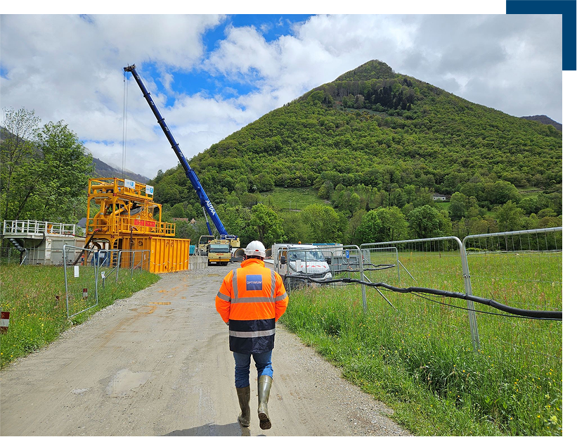
Different trenchless techniques
Each trenchless crossing is unique. A variety of trenchless techniques exist, each with its own characteristics and advantages.
Auger boring
Horizontal Directional Drilling
Direct Pipe®
Microtunnelling
Tunnelling
Choosing the right technique depends on several factors: customer requirements, crossing dimensions, industry regulations, and the geological and geotechnical conditions of the jobsite. After a thorough analysis by trenchless specialists, one technique will stand out, either from a technical or an economical perspective.
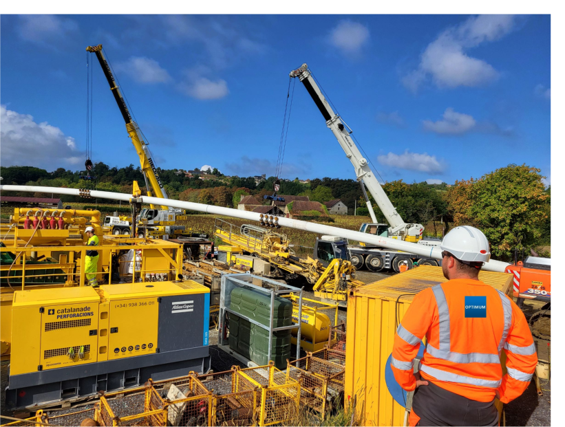

Auger boring / Horizontal drilling
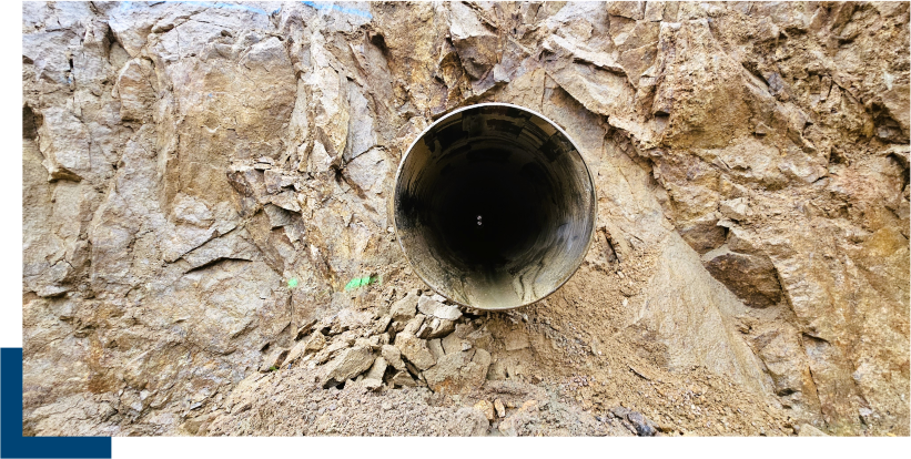
Efficient techniques for reduced length crossings
While basic, boring techniques are very efficient in specific terrains and contexts. They ensure the hole is maintained open as construction progresses and pass under obstacles by creating a straight path between two excavated pits / shafts. These techniques can be equipped with simple guidance systems and are ideal for rectilinear structures, typically up to 120 meters in length.
Three principal techniques exist
Auger boring
Down-the-hole hammer drilling
Pipe ramming
Auger boring
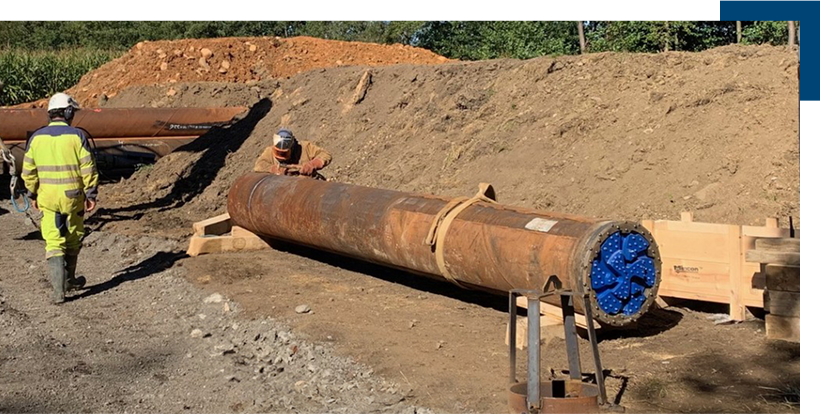
Auger boring is a technique used in soft ground, where a steel pipe is pushed into the earth from a launch pit. As the tube advances, a helical auger excavates the soil in place.
The process relies on a drill bit at the front of the pipe, which rotates to excavate the ground as the tube progresses forward.
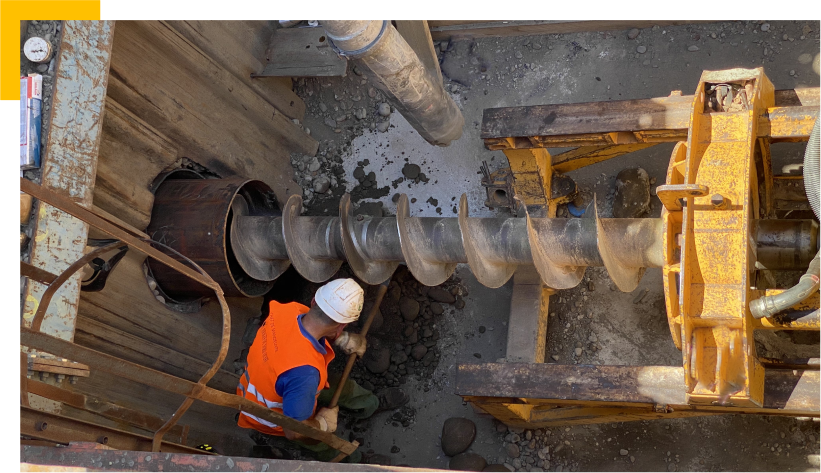
Auger boring: At a glance
Advantages
Smaller length crossings
Drilled hole maintained
Suitable ground conditions
Soft ground
Soft rock
Coarse ground (with adapted tooling)
Dimensions
Diameters from 300mm to 1400mm
Lengths of less than 140m
Down-the-hole hammer drilling
For rock formations or those with significant blocometry, the traditional drill bit is replaced by a pneumatic hammer.
The hammer breaks up the ground in front of it, with the crushed material being evacuated to the launch pit via an auger. Progresses continues, pipe after pipe, until the reception pit is reached.
Down-the-hole hammer drilling: At a glance
Advantages
Smaller length crossings
Crossing rocky terrain or terrain containing blocks
Drilled hole maintained
Suitable ground conditions
Pebbles and blocky gravel
Rocks
Dimensions
Diameters from 350mm to 1200mm
Lengths of less than 120m
Pipe ramming
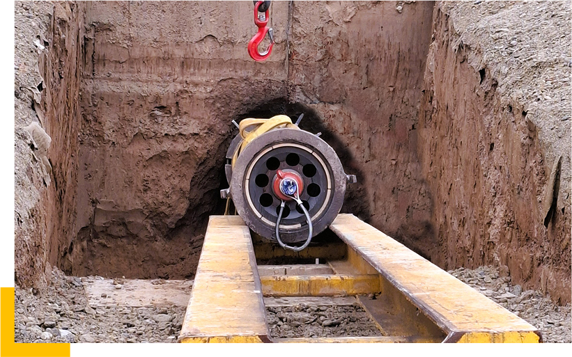
Pipe ramming involves driving an open pipe into the ground from a launch pit using impact force. Although this method is more basic and unguided, it remains effective for low linear projects and areas near the water table.
As the ramming process continues, the pipe collects the displaced ground until it reaches the reception pit. Once in place, the pipe is emptied using hydraulic or mechanical methods, leaving a steel pipe in position, ready for installation of the network or pipeline.
Pipe ramming: At a glance
Advantages
Lower costs
Drilled hole maintained
Suitable ground conditions
Soft and fine soils
Soft and gravelly soils
Dimensions
Diameters from 300mm to 1400mm
Lengths of less than 80m
Horizontal Directional Drilling
Rapid execution with limited environmental impact
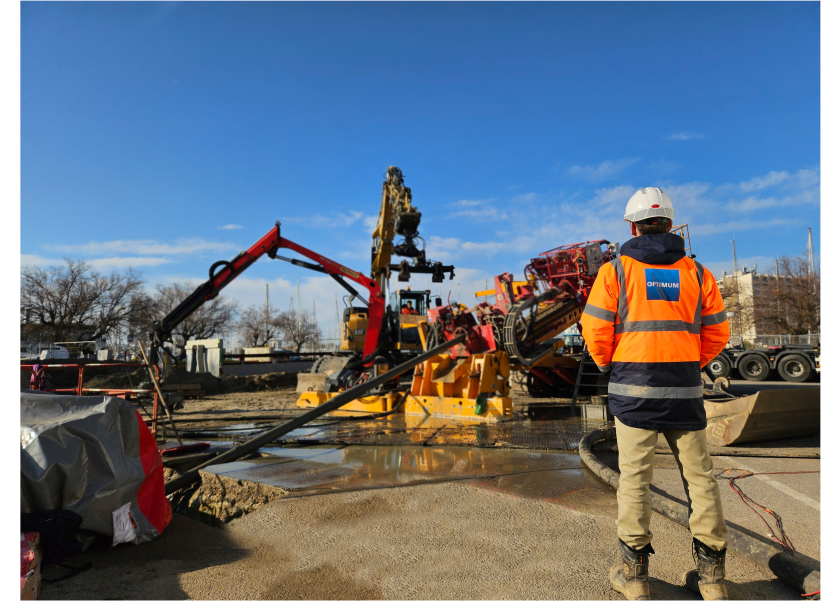
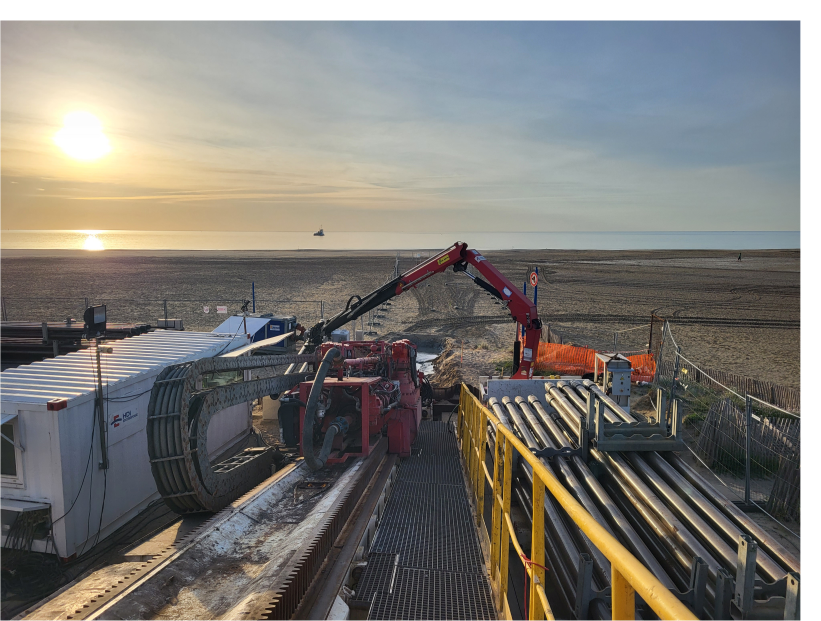
Horizontal Directional Drilling (HDD) often offers the advantage of being quick to implement and cost-effective. HDD is a widely used technique for crossing obstacles such as rivers or roads. It involves drilling directly from the surface of the ground along a predefined, inverted arc-shaped path.
Horizontal Directional Drilling typically proceeds in three stages
Pilot Hole: This creates the drilling profile, one rod at a time, connecting the entry point to the exit point.
Reaming: This expands the diameter of the hole in one or more passes until it is 30% to 50% larger than the pipe or network to be installed. If the pilot hole’s diameter is sufficient, reaming may not be necessary.
Pullback: This is the phase where the pre-assembled pipe or network is pulled into the reamed hole in one continuous section.
Drilling Fluids
A drilling fluid is systematically injected into the drilled hole at each stage of Horizontal Directional Drilling (HDD) (pilot hole, reaming, and pullback operations). This fluid helps lubricate and cool the drilling tools, stabilize the drilled hole, and, most importantly, carry soil debris out of the hole.
The fluid is injected under pressure through rods and exits through the drilling tools inside the hole. It is typically a mixture of fresh water and bentonite, although its composition, quantity, and density can be adjusted based on the soil characteristics and site constraints.
More complex drilling fluids also exist, such as those made from polymers or seawater, which can be especially useful for landfall projects.
Horizontal Directional Drilling (HDD): At a glance
Advantages
Quick execution
Direct installation of pipelines
Work directly from the surface
Limited environmental impact
Suitable ground conditions
Sands (<2 mm)
Silts
Clays
Homogeneous, unfractured rocks
Dimensions
Diameters from 50mm to 1400mm
Lengths from 10m to 5000m
Direct Pipe®
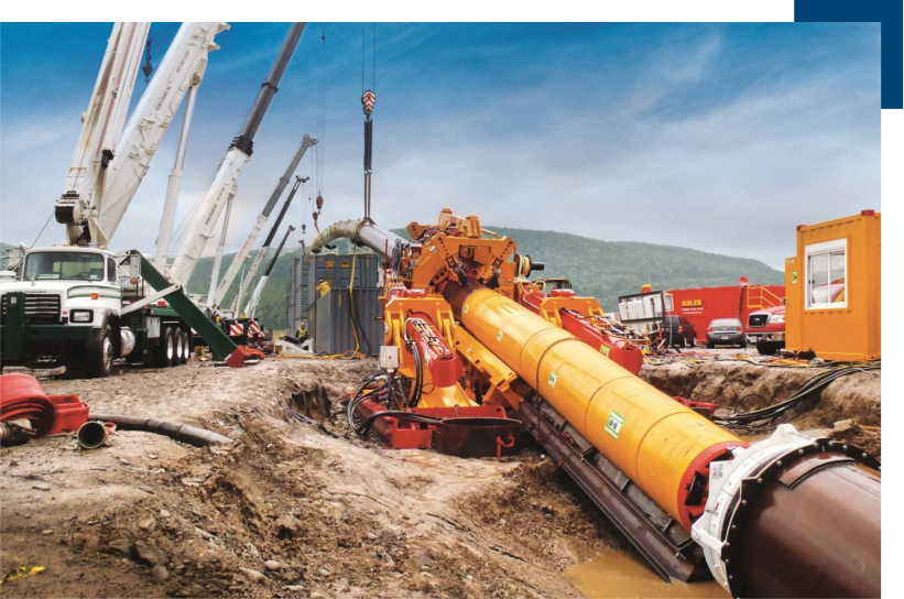
An innovative technique for complex trenchless crossings
Direct Pipe®, by Herrenknecht AG, is an innovative technique that combines the advantages of both Horizontal Directional Drilling (HDD) and microtunnelling. It allows for work to be carried out directly from the surface without the need for deep excavated entry and exit shafts, whilst also benefiting from microtunnelling technology, which enables tunnelling through almost all types of terrain with unmatched precision.
This technique is particularly well-suited for landfall projects as it minimizes offshore mobilisation requirements. It is also relevant for crossings where the geological conditions make HDD implementation unfeasible.
Direct installation by Pipe Thrusters
Direct Pipe allows for the direct installation of steel pipes (coated or uncoated) following an inverted arc profile, similar to those constructed using the HDD technique. The excavation tool connected at the front of the steel pipe is an AVN-type microtunnel boring machine (TBM), while the push force required is transmitted through the steel pipe, pushed from the surface by a Pipe Thruster. Located at the entry point, the Pipe Thruster uses « circular jaws » to grip the steel pipe, in 5-metre sections, and apply a longitudinal push force of up to 750 tons without damaging the pipe. If necessary, multiple Pipe Thrusters can be connected, one behind the other, to increase the push force available.
The steel pipe is assembled at the surface, behind the thrusters, in one or more sections depending on the site conditions, minimizing as far as possible the number of intermediate welds required. In this way, a long Direct Pipe installation can be carried out without having the entire pipe length behind the thrusters at any one time. Each steel pipe section must be pre-equipped with all the necessary connections to operate the microtunnel boring machine (energy, marine lines, lubrication, communication, etc.).
Finally, the steel pipe installed by Direct Pipe can serve as either the final structure or as a casing for networks installed inside it.
Direct Pipe : At a glace
Advantages
Work directly from the surface
High thrust force capacity
Adaptable for all ground conditions
Pipe stability
Reduced jobsite surface
Suitable ground conditions
All ground conditions
Dimensions
Diameters from DN750 to DN1500 (30″ to 60″)
Length from 400m to 2000m
Microtunnelling
Precise and flexible tunnelling in all ground conditions
The most sophisticated tunnelling technique, microtunnelling, is applicable in a wide range of geological formations and allows for precise control over key mechanical and hydraulic parameters, as well as the drill trajectory. The technique is particularly advantageous as it mechanically supports the tunnel as construction progresses and allows for great flexibility in the geometrical design of the structures.
The microtunnel boring machine (MTBM) used is usually an AVN type: a hydraulic machine that enables both control of the hydraulic pressure at the cutting face as well as the transportation of the excavated material back to the surface.
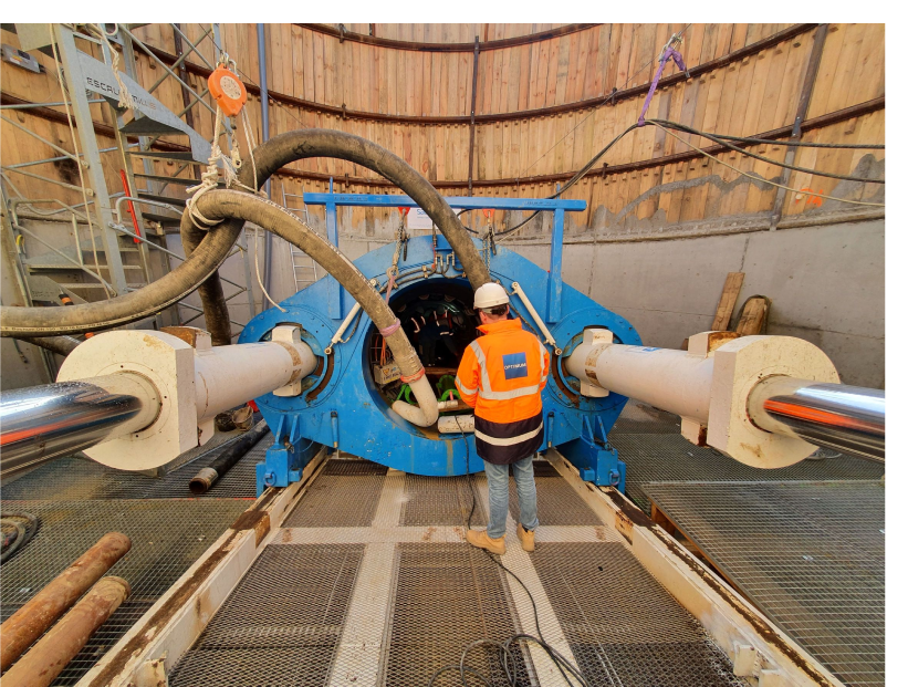
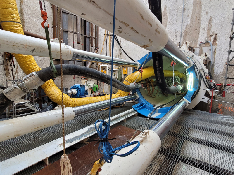
Excavated ground maintained throughout construction
Microtunnelling involves excavating a tunnel from a launch shaft and advancing concrete, GRP, or steel pipes behind the microtunnelling machine as it progresses. As tunnelling continues, the entire microtunnel system moves forward, powered by a thrust system installed in the launch shaft.
A lubrication fluid, injected at the upper surface of the microtunnel, lubricates the system to reduce friction between the tunnel and the surrounding ground.
Microtunnelling at a glance:
Advantages
Precision and ability to achieve complex geometries
Excavated ground supported during construction
Waterproof structures, potentially accessible after completion
Suitable for gravity-flow networks
Suitable ground conditions
Almost all geotechnical conditions
Dimensions
Diameters from 500mm to 4000mm
Lengths up to 2000m
Tunnelling
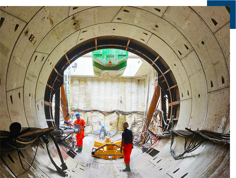
A technique for large diameter and long linear structures
Similar to microtunnelling, from which it is derived, tunnelling allows for the excavation of larger diameter structures. This technique also enables the use of various machine technologies for greater control over the excavation process, further reducing soil-structure interactions.
During excavation, unlike microtunnelling, prefabricated segments are placed inside the tunnel, to form it’s structure. This assembly of individual segments, rather than the installation of complete pipe rings, significantly facilitates the construction of large-diameter tunnels. The completed sections of the tunnel then support the boring machine as it progresses, allowing for the construction of very long structures.
